MNS matala paine vetopaneli
Tämä sarja matalajännitteisiä vetokontaktikkeja on modulaarinen tehtaassäädös (FBA) kaappi, jonka teknologia on saavuttanut kansainvälisen tason 1990-luvun lopulla. Tämä sarja matalajännitteisiä vetokontaktikkeja sopii sähköjärjestelmien voimanmuuntamiseen, -jakeluun ja -ohjaamiseen laitteistossa, jonka nimellinen työjännite on AC 50~60Hz ja alle AC 660V:ssa elektroniikkatehoasemissa, muuntamoissa, petroksessa, metalliteollisuudessa, teräsliukastuksessa, liikenteessä, energiassa, kevyessä teollisuudessa, tekstiiliteollisuudessa ja muissa tehtaissa sekä kaivoksissa, asuinalueilla, korkeustaloissa ja muissa paikoissa.
Laite täyttää GB7251.1 -normin "Matalajännitteinen vaihdeasemakokoonpano" ja JB/T9961 -normin "Matalajännitteinen vetovaihdeasemakokoonpano" kansalliset ammattinormit sekä on yhteensopiva IEC439-1:n, VDE0660 osa V ja muiden kansainvälisten ammattinormien kanssa.
Tavalliset toimintaympäristön ehdot
1. Ympäristöilmaston lämpötila ei saa olla korkeampi kuin +40C, eikä alempi kuin -5C, ja sen keskilämpötila ei saa ylittää +35C 24 tunnin aikana.
2. Ilmakehitys: Ilma on puhdas, ja suhteellinen kosteus ei ylitä 50% korkeimmalla lämpötilalla +40C. Suurempi suhteellinen kosteus on sallittu alhaisemmilla lämpötiloilla, kuten 90% +20C lämpötilalla. Kuitenkin huomioon tulisi ottaa lämpötilan muutokset, jotka saattavat aiheuttaa välikausisen kondensaation.
3. Korkeus ei saa ylittää 2000m.
4. Tämä laite on soveltuva kuljetukseen ja varastointiin lämpötiloissa, jotka vaihtelevat -25 °C:sta +55 °C:een, enintään +7 °C lyhyen ajan (ennen kuin 24 tuntia). Näissä äärimmäisissä lämpötiloissa laitteen ei tulisi kärsiä mitenkään korjattavista vahingoista, ja se tulisi toimimaan normaalisti normaalissakin tilanteessa.
5. Jos edellä mainitut käyttöehdot eivät voi toteutua, asia ratkaistaan käyttäjän ja valmistajan välisen neuvottelujen kautta. 6. Kun tämä laite käytetään merellisillä öljynporaus- ja tuotantotalouksilla sekä ydinvoimaloissa, erillinen tekninen sopimus tulisi solmittaa.
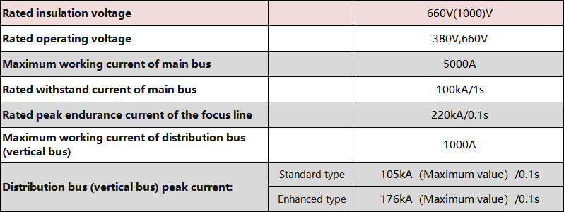
Perustekniset parametrit

2. Suojeluaste
Noudattaa IEC529:n ja DIN40050:n standardeja
IP30 kiinteän suojelun osalta suuremmasta kuin 2,5 mm
IP40 kiinteän suojelun osalta suuremmasta kuin 1,0 mm halkaisijasta
IP54 tarjoaa suojelua hienolta ja vedestä missä tahansa suunnasta
kaappirakenne
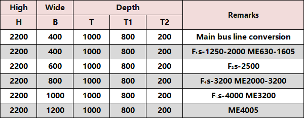
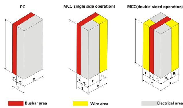
Kuormituksen kaapin perusrakenne koostuu C-muotoisista profiileista, jotka muovutetaan E=25mm moduuliasennushyppymäärityksellä olevista teräslehdysten. Kaikki kaapit ja sisäiset jakopaneelit ovat galvanisoituja ja puhdastettuja. Ympäröivät ovenpaneelit ja sivupaneelit käsitellään korkeajännitteisessä elektrostaattisessa maalauksessa. Kaapin perusrakenne näkyy kuvassa 1: kaapin perusmitat näkyvät kuvassa 2. Taulukot 1 ja 2.
Kaapin tyyppi
1. Sähköjakokeskuskaappi (PC): Voit käyttää Emax-, MT3WNAH- ja ME-sarjojen sekä muita johtepuhujia.
2. Moottorien hallintakeskuskaappi (MCC: koostuu suurista ja pienistä vetokomponenteista, joiden päävaihde on korkeaeristyskykyinen muovikansiomainekesytys vaihtelee tai pyörivä kuormavaihde, jossa on polttimoottoreita jokaiselle yksilölliselle päävaihdelle. Tehoosion automaattikompensaattori (manuaalisesti, automaattisesti ja etätehoosion kompensaatiolaitteilla).
Sähköjakokeskus (PC) -kaappi

Moottorien hallintakeskus (MCC) -kaappi

Kaapin kehysrakenne koostuu C-muotoisista profiileista (kuva 1)

Kaapin kaavio (kuva 2)

Kaapin kappaleen jakoluonteen suunnittelu
1. Medium (PC)
(1) PC-kaapin sisäosa on jaettu kolmeen osa-alueeseen;
Vaakasuuntainen busbaarikomparteemi: kaapin takana;
Funktiokomponenttien komparteemi: sijaitsee kaapin edessä yläosassa tai vasemman puolella;
(2) Vaakasuuntainen busbaarikomparteemi on eristetty funktiokomponenttien komparteemista teräslevyillä. Ohjauskytkentöjen komparteemi ja funktiokomponenttien komparteemi ovat eristetty flamiiniestä polyfenyylieteri-plastikeilosta.
(3) Kaapissa asennetut raamityypit kuljettimet voidaan käyttää manuaalisesti kaapin ulkopuolella oven suljettaessa. Seuraa kuljettimen avoimuustilan tilaa ja määritä, onko kuljettin testiasennossa vai työasennossa perustuen toimintomekanismin ja oven paikkasuhteisiin.
(4) Komponenttijakorakenne on suunniteltu pääpiiriksen ja apupiiriksen välille, ja apuliikenteollisuuden yksikkö, joka koostuu mittarinsignaalivaloista ja painikkeista, on asennettu materiaalipaneeliin, jonka takana käytetään lieventävää polyuretaanipensoa.
Muovista tehty peite on eroteltu pääpiiriksestä.
2. Vetokelpoiset moottorien hallintakeskukset ja pienvirtaisten virtajakaokeskukset (MCC)
MCC-kokoonpano (Motor Control Center), josta voidaan vetää laatikot, on jaettu kolmeen osa-tilaan: vaakasuuntainen buskilinjakotila takana kokoonpanon takana, toimintayksikön tila kokoonpanon vasemmassa edessä ja kabelitila kokoonpanon oikeassa edessä. Vaakasuuntainen buskilinjakotila ja toimintayksikön tila on erottelty funktioplitteistöillä, jotka koostuvat hienopyyhkeestä palasiirtymisesteisestä muodostelmasta, ja kabelitila on erottelty vaakasuuntaisesta buskilinjakotilasta ja toimintayksikön tilasta teräslevyillä. MCC:n laatikot (Motor Control Center) ovat jaettu seuraaviin 5 tyyppeihin:
8E/4: Korkeus 200x Leveys 150x Syvyys 400mm
8E/2: Korkeus 200x Leveys 300x Syvyys 400mm
8E: Korkeus 200x Leveys 600x Syvyys 400mm
16E: Korkeus 400mm x Leveys 600mm x Syvyys 400mm
24E: Korkeus 600mm x Leveys 600mm x Syvyys 400mm
3. Takaosainen ulosjohtovirtakokoonpanon rakenne
Takaperäinen ulosmenon johto on suunniteltu vähentämään kuhdastaajan laajennusta. Kuhdastaajan pääjohto asennetaan vaakatasoon kuhdastaajan yläosassa, ja kaapin takainen puolikas on kaapelikompartimendi. Saapuvat ja lähtevät kaapelit ovat kaikki kytketty kaapelikompartimendissa kaapin takana. Kuhdastaajan edessä on laitekompartimendi, joka sisältää kuhdastaajan toimintayksiköt. Järjestelmän suunnittelu siirtää kuhdastaajan sivulla olevat kaapelit taakse suljettuun kaappiin, mikä vähentää merkittävästi kuhdastaajan laajennusta ja täyttää entistä paremmin alustan tila-asettelun vaatimuksia.
Liittymäkoneen mitat ovat 600mm leveinä ja 1000/1200mm syvyyden suhteen. Yläosa on erillinen pääjännitysosasto, joka on eristetty laiteosastosta. Etualan laiteosaston tehokas asennuskorkeus on 72E (E=25mm), mikä on eristetty takakableosastosta monifunktion laidalla, hyödyntämällä täysin konsenttien asennussyötä. Rakenne on tiivis ja yksikön konfiguraatio joustava. Takaostrupussa on ovi helpottamaan asennusta ja huoltoa. Liittyvän kaapin leveys määritetään liittyvän yksikön kehitysvirta-perusteella, suositeltuja leveyksiä ovat 400/600/800/1000mm ja kaapin syvyys 1000mm.
Bussijärjestelmä
Kilpikonna voidaan varustaa kahdella pääjännitysradalla, jotka asennetaan kilpikonnan takaisessa jännitysradan komparteissa. Kaksi jännitysradan sarjaa voidaan asentaa erillään kaapin ylä- ja alaosiossa. Tulojohtojen tarpeiden mukaan ylä- ja alasijaiset jännitysradat voivat olla eri tai saman poikkileikkauksen materiaaleja. Molemmat voidaan ravitella erillisesti, rinnakkain tai varakäyttöön.
Jakaamisbussi (pystysuuntainen bussi) on montattu liehdonkestävään muovifunktioitauluun ja kytketty pääbussiaan erityismittareilla, jotka estävät ei vain kaarimisen aiheuttaman laskutuksen, mutta myös ihmisten kosketuksen. Kaapeliin on varustettu itsenäinen PE-maaranjärjestelmä ja N-neutraalijohde. Molemmat kulkevat koko laitteen läpi ja asennetaan kaapelin pohjaan ja oikeaan sivuun. Jokaisella piirrellä voi olla yhteys lähimpään maara- tai neutraaliyhteyteen. Koko bussijärjestelmän asennus näytetään kuvassa 3. Kaikki kaapelirunkon rakenteelliset osat ovat kytkettyjen itsekiintyviin skruujiin, mikä takaa korkean maaran luotettavuuden.
Neutraali bussi ja neutraalin suojabussi on asennettu funktionaalisen yksikön kompartimentin alempaan osaan suorina ja pystysuorassa kaapelikompartimessa. Jos eristin käytetään N-janan ja PE-janan eroittamiseen, niiden on oltava erillään. Jos johto käytetään kahden janan lyhdistämiseen, ne muuttuvat PE/N-janoiksi.
Suojamaalajärjestelmä
Laiteen suojauspiiri koostuu kahdesta osasta: erillisesti asennetusta PE-kaapelistä (tai PE/N-kaapelistä), joka kulkee koko järjestelmän pituudessa, sekä johtavista rakenteellisista osista. Laiteen metalliset rakenteelliset osat, paitsi ulkopöydät ja sulkipaneelit, ovat kaikki galvanisoituja. Rakenteellisten osien yhteyksissä ne on suunniteltu huolellisesti tietylle lyhytaikaiselle virtalle vastustamaan.
Apukäytävät ja kaapelirakenteet
Funktiokomparteemin yläosa on varustettu apukolmioketjun kanssa, joka voi sisältää kaapeliyhteydet ja julkiset sähköjohtot.
Kabelin ja ohjausjohto yhteys
Vedettävän komponentin toisella puolella kabelikomparteemissa on laitteita ja päätteitä, jotka kytketään lähteviin sähkö- ja ohjausjohtoihin. Saapuvat ja lähtevät kabelit ja ohjausjohtojen laitteet ovat aseteltuja rautalangalla kabelikomparteemin oikealla puolella. Pääkierroksen pääte on sijainnilla takana, ja ohjausjohto pääte on eteenpäin 45 ° suunnassa. Ohjausjohtopääte voidaan kytketä skruuilla tai pistepäätein tai kuparipidin kanssa. Jos vedettävän komponentin adapterin pääkierroksen pääte on alle 63A, se on varustettu PE-päätteen kanssa.
Turvakilpailujärjestelmä
Jokainen kaapeli on varustettu yhdellä tai ryhmällä hienoilla plastisilla toimintalautailla, jotka on asennettu pääjohtopaneelinhuoneen ja sähköhuoneen välille. Niiden tehtävä on estää tehokkaasti onnettomuuksia, jotka johtuvat busseja vikaan johtavista kytkimetiedoista aiheuttamasta salama- ja lyhytjyrkistymisestä sekä ottaa käyttöön ankaria erottelutoimenpiteitä.
Ylä- ja alaputkien välillä on galvanisoitu metallipohjaplankki ilmaporauksilla erotteluun. Pienemmät 8E/4- ja 8/2-putkit ovat ympäröitytulevasteisilla insinöörimateriaaleilla, joten naapurikolmioiden välillä on voimakasta isolointi- ja erottelutoimintoa. Kaapelissa käytetään monia muovikomponentteja elossa olevien osien tukemiseksi, jotka ovat hapolittomat ja niillä on CT1300-tason yläpuolella oleva antiilmaantoiminta.

Ystävällinen tiimimme haluaisi kuulla sinusta!